Table of Contents >> Show >> Hide
- Why Optical Fiber Is Traditionally Hard to Make
- Where 3D Printing Fits: The “Print-and-Draw” Idea
- What Makes This Method “Simpler” (and What It Doesn’t Simplify)
- Real Examples of 3D Printing in Optical Fiber Fabrication
- Design Choices That Matter in 3D-Printed Fiber Approaches
- Where 3D-Printed Fiber Methods Shine
- Common Myths (Let’s Gently Roast Them)
- What’s Next: Toward Practical 3D-Printed Optical Fiber Ecosystems
- Conclusion
- Field Notes: of “Experience” Prototyping 3D-Printed Fiber Ideas
Optical fiber is one of those modern miracles that feels downright unfair: a strand thinner than a noodle can carry the entire internet’s mood swings across oceans.
The catch? Making “real” optical fiber has traditionally required expensive gear, ultra-clean manufacturing, and processes that look like a cross between a chemistry lab and a glass-blowing competition.
That’s why the idea of using 3D printing to simplify optical fiber fabrication has such big “wait… seriously?” energy.
Spoiler: you’re not 3D-printing a kilometer of telecom-grade fiber on your desktop printer like it’s a Benchy.
The most practical “simpler method” is usually a print-and-draw workflow3D print a larger “preform” (a scaled-up version of the fiber’s cross-section),
then use professional thermal drawing equipment to pull it into a thin fiber. It doesn’t erase the hard parts, but it can remove a lot of tedious, expensive, geometry-limiting steps.
In this article, we’ll break down what “simpler” really means, what researchers have already demonstrated with 3D-printed preforms (polymers and even silica),
where the approach shines (microstructured and specialty fibers), and where it still hits reality (purity, loss, and the laws of physics being party poopers).
We’ll finish with a 500-word “field notes” section: the kinds of experiences teams commonly run into when prototyping 3D-printed fiber concepts.
Why Optical Fiber Is Traditionally Hard to Make
The preform-to-fiber pipeline (a.k.a. “scale it down without messing it up”)
Most optical fiber starts life as a preform: a large glass rod that already contains the fiber’s core-and-cladding structure, just at a much bigger size.
That preform is heated in a draw tower and pulled into a long, thin fiber while tightly controlling diameter, concentricity, and surface quality.
Even tiny defects can increase optical loss, scatter light, or weaken the fiber.
For telecom fiber, the bar is brutally high. You’re chasing extremely low attenuation, consistent refractive index profiles, and glass purity so extreme that “just melt sand”
is basically a comedy routine. Traditional methods (various vapor deposition processes, consolidation, and drawing) are optimized for mass production and performancebut
they’re not designed for rapid experimentation with weird new shapes.
Microstructured fibers: the geometry problem
Some of the most exciting fibers aren’t simple “solid core, solid cladding” designs. Microstructured optical fibers (including photonic crystal and hollow-core designs)
use patterns of air holes or complex internal features to guide light in unusual ways. These are often made with “stack-and-draw” methods:
assemble many tiny capillaries and rods into a larger bundle, fuse them, then draw.
Stack-and-draw works, but it’s labor-intensive and can limit what shapes are feasible. If your dream fiber cross-section looks like a snowflake wearing a top hat,
the traditional toolbox may politely suggest you lower your expectations.
Where 3D Printing Fits: The “Print-and-Draw” Idea
The simplest way to explain the 3D-printing approach is this:
3D printing replaces some of the complex preform fabrication steps, especially for structured geometries.
Instead of machining, stacking, drilling, or assembling multiple parts, you can digitally design a preform and print itoften in polymer first, and in some cases in glass-related materials.
Then, the printed preform is thermally drawn into fiber using established drawing techniques.
3D-printed preforms for air-structured fibers
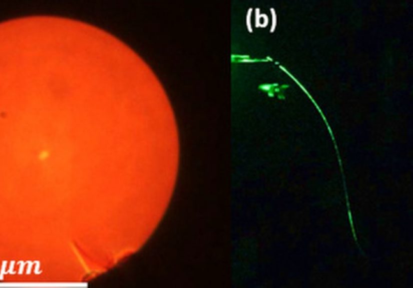
One of the earlier headline demonstrations showed that you can draw an air-structured fiber from a 3D-printed preform.
That matters because air holes are exactly the kind of geometry that’s annoying to manufacture by hand, but relatively straightforward to model and print.
When you draw the preform, those millimeter-scale holes can shrink to micron-scale featuresturning a chunky plastic “prototype” into a real fiber geometry.
This is the heart of the “simpler method”: 3D printing makes the preform geometry easier and faster, even if the final draw still requires specialized equipment.
In other words, it can simplify the part that’s most design-limiting (the internal structure) without pretending a desktop printer can replace industrial draw towers.
From polymer prototypes to silica: why that leap is a big deal
Polymer optical fibers can be useful for sensors, short-distance data links, education, and prototypes. But for the backbone-of-the-internet stuff, silica is king.
Researchers have demonstrated silica optical fiber drawn from 3D-printed preforms, showing both single-mode and multimode behavior.
That’s important because it signals that additive manufacturing can reach beyond “plastic demo fibers” and into glass-based optical fiber concepts.
The key nuance is that “3D printing silica” often involves printing a form that is later processed (for example, converted and consolidated) into a glass preform suitable for drawing.
The workflow is still challenging, but it expands the design space dramaticallyespecially for specialty fibers where geometry is the whole point.
What Makes This Method “Simpler” (and What It Doesn’t Simplify)
What it simplifies
- Geometry prototyping: Complex internal structures can be designed in CAD and produced without painstaking stacking, drilling, or multi-part assembly.
- Iteration speed: If a hole pattern collapses during draw or a core shape isn’t stable, you can adjust the digital design and try again faster.
- Customization: Specialty fibers (sensors, lab tools, unusual waveguides) benefit from “small-batch, high-variety” manufacturing.
- Access for research: Labs can explore fiber structures that would be impractical or too expensive to fabricate traditionally.
What it does not simplify (at least not yet)
- High-performance purity requirements: Telecom-grade fiber still demands extreme material purity and tight control over defects.
- Thermal drawing complexity: Drawing fiber requires precise control, monitoring, and safety infrastructure.
- Optical loss challenges: Print lines, inclusions, bubbles, and surface roughness can increase scattering and attenuation.
- Scaling to mass production: 3D printing may be ideal for specialty designs, but not necessarily for commodity fiber volumes.
Real Examples of 3D Printing in Optical Fiber Fabrication
1) Air-structured fibers from printed polymer preforms
Demonstrations of air-structured fibers drawn from 3D-printed preforms are a foundational proof that internal geometry can survive the draw processat least well enough
to form functional waveguiding structures. Even when optical loss is higher than commercial fiber, these results validate the concept and provide a platform for refining
printing materials, preform design, and draw conditions.
2) Silica fiber drawn from 3D-printed preforms
The step from polymer to silica is significant because silica dominates long-distance, high-performance optical transmission.
The research community has shown that 3D-printed preforms can be used to produce silica fibers with meaningful waveguiding behavior,
suggesting that additive manufacturing can play a role in next-generation glass fiber designsnot just polymer demonstrations.
3) Microstructured fiber designs pushing resolution
More recent “print-and-draw” work has aimed at microstructured fibers with finer and finer features, including hollow-core and anti-resonant structures.
Reports describe printing long preforms with thin walls and then processing them into fibers where sub-micron-scale features can be realized after draw-down.
That’s exciting because microstructured fiber performance is extremely sensitive to geometry.
4) Direct 3D printing of polymer optical fibers (the “good enough” lane)
Another branch of work explores printing polymer optical fibers directly (or printing fiber-like waveguides and sensor fibers) using common 3D-printing methods.
These approaches can be attractive for education, prototyping, and sensing applications where you don’t need telecom-grade attenuation.
Think of it like the difference between a concept car and a delivery van: both are vehicles, but only one needs to survive a million miles.
Design Choices That Matter in 3D-Printed Fiber Approaches
Material choice: polymer vs glass (and the “in-between” strategies)
Polymers are easier to print and can still be optically useful, especially for short distances, sensors, and visible-light demonstrations.
But polymer fibers often have higher loss than silica and different thermal/mechanical behavior.
Glass provides superior long-term stability and lower loss potential, but printing and processing glass (or glass precursors) is much harder.
Many “3D-printed silica” workflows are hybrid: print a structure that can be transformed into a glass preform through thermal processing and consolidation,
then draw. This hybrid approach keeps the digital design freedom of 3D printing while still ending with a silica-based fiber.
Geometry: holes, cores, and the problem of “will it collapse?”
The draw process shrinks everything. That’s good for resolutionbut it also means small design issues get magnified.
Air holes can collapse, walls can distort, and asymmetry can become a built-in feature (whether you wanted it or not).
Designers often add structural “insurance” into the preform: thicker walls, supportive webs, or shapes that are known to stay open during drawing.
Surface quality and scattering
Optical loss is often the make-or-break metric. Many 3D printing methods produce layer lines and surface roughness.
When scaled down into fiber dimensions, those imperfections can scatter light and increase attenuation.
Post-processing (polishing, thermal smoothing, consolidation steps, and improved print parameters) can help,
but it’s one reason 3D-printed fibers are often positioned as specialty or prototype solutions rather than immediate telecom replacements.
Refractive index control (the doping reality check)
Traditional fiber manufacturing has sophisticated ways to control refractive index through dopants and deposition profiles.
Additive manufacturing methods are still catching up in achieving that same level of index precision and repeatability.
That said, research has shown progress toward multi-material and doped structures in fiber-related workflows,
which could unlock custom devices and functional fibers where “perfect telecom specs” aren’t the only goal.
Where 3D-Printed Fiber Methods Shine
Specialty and research fibers
If your objective is to explore new guiding mechanisms, unusual mode shapes, or complex microstructures, 3D printing can be transformative.
It enables quick exploration of shapes that would be very hard to fabricate using stacks of capillaries and hand assembly.
Sensors and harsh-environment concepts
Optical fiber sensors don’t always need kilometer-scale performance. Many sensing applications are local:
measure strain, curvature, temperature, or light interaction over short lengths.
That makes 3D-printed polymer fibers and specialty preform designs particularly attractive, especially when the sensor geometry is part of the innovation.
Education and “visible proof” demonstrations
There’s real value in making fiber optics tangible. A printed preform that becomes a functional fiber after drawing is a powerful teaching tool:
it helps students understand core/cladding, waveguiding, and how microstructure shapes light.
It also demystifies fiber as “not magic, just very carefully controlled physics.”
Common Myths (Let’s Gently Roast Them)
Myth: “I can print fiber optic cable at home now.”
Not really. The “simpler method” still relies on controlled thermal drawing and safety infrastructure.
3D printing helps with preform geometry and experimentation, not replacing industrial-scale drawing for high-performance fiber.
Myth: “If it guides light, it’s the same as telecom fiber.”
Guiding light is step one. Telecom fiber is step one plus a hundred other steps: ultra-low loss, durability, consistent diameter, low defect density,
protective coatings, and rigorous testing. Many 3D-printed approaches are best thought of as enabling new designs and specialty functions,
not instantly dethroning mass-produced fiber.
What’s Next: Toward Practical 3D-Printed Optical Fiber Ecosystems
The trajectory is clear: better printable materials, higher-resolution printing, improved consolidation and surface finishing,
and smarter design rules for draw stability. The most promising near-term outcome isn’t “replace all fiber factories,”
but rather enable a parallel ecosystem:
small-batch, high-complexity fibers and fiber devices that can be digitally designed, rapidly prototyped, and drawn into functional components.
In the long run, as glass additive manufacturing matures and multi-material printing improves, we may see more integrated workflows:
printed preforms with embedded structures, tailored index profiles, or built-in device regionsturning the fiber itself into a platform for photonic devices,
not just a light pipe.
Conclusion
A “simpler method to make optical fiber with 3D printing” doesn’t mean fiber manufacturing becomes trivialit means the most design-limiting step,
making complex preforms, can become more digital, faster, and more creative.
The print-and-draw approach has already proven that 3D-printed preforms can become functional fibers, including structured polymer fibers and even silica-based fibers.
The biggest wins today are in specialty geometries, research, sensors, and rapid prototypingareas where flexibility and iteration matter as much as ultra-low loss.
If the future of fiber optics includes more custom shapes, multi-function fibers, and device-like behavior along the fiber length,
3D printing is shaping up to be less of a gimmick and more of a serious manufacturing partnerone that speaks fluent CAD and doesn’t complain when you ask for six holes,
a weird core shape, and a “tiny optical labyrinth” before lunch.
Field Notes: of “Experience” Prototyping 3D-Printed Fiber Ideas
Here’s what teams commonly report when they experiment with 3D printing for optical fiber conceptswritten like practical field notes, not a lab instruction manual.
First: the CAD phase feels deceptively easy. You model a clean cross-section, add air holes, maybe a funky core shape, and everything looks perfect on-screen.
Then reality introduces itself through a very small, very stubborn detail: manufacturability. Holes that are too thin-walled can distort during printing.
Internal features that look crisp in CAD may print slightly oval, slightly rough, or slightly “why is that corner doing that?”
Next comes the “printing sanity loop”: print, inspect, adjust, repeat. Early prototypes often focus on geometry survival rather than optical perfection.
People learn quickly that uniformity matters more than artistry. A small asymmetry in the printed preform can become a meaningful asymmetry after draw-down.
If the design depends on a perfectly centered core, the team may end up adding alignment features or redesigning supports in the preform to keep the structure stable.
There’s usually a moment when someone says, “So… the preform is basically a suggestion, and the draw process is the editor.” That’s not wrong.
Optical testing at the prototype stage tends to be simple and revealing. If a sample guides light at all, that’s a milestone.
The next questions are: how much light makes it through, how sensitive is it to bending, and does the output look stable or speckled?
Many groups see higher scattering than expectedoften traced back to surface roughness, tiny inclusions, or micro-bubbles.
That leads to discussions about post-processing, better materials, or alternative printing methods with smoother internal surfaces.
The most valuable “experience” is learning how design choices translate through scaling.
A hole pattern that looks generous in a preform can become razor-thin at fiber dimensions.
A wall thickness that seems safe can become fragile. Teams often start building informal design rules:
“This hole spacing survives,” “that wall collapses,” “this web supports the structure,” “that corner creates stress.”
Over time, the workflow shifts from “print what we want” to “print what the draw will respect.”
Finally, there’s the emotional arc: initial excitement, a few confusing failures, then steady progress as the team learns the combined system.
When a redesigned preform finally draws into a stable fiber geometry, it feels like winning a tiny Nobel Prizeuntil someone asks about optical loss numbers.
That’s the moment the group remembers the real point: 3D printing doesn’t magically eliminate the hard parts of fiber optics.
It moves the innovation frontier to geometry, customization, and rapid iterationwhere “good enough to test the idea” is often the breakthrough that enables the next, better version.